Digital Audio
Introduction
In this lab, I used the STM32L432KC microcontroller to play music by generating square waves through timer-controlled PWM output. The MCU’s PLL was set to a stable 80 MHz system clock, which was then routed into two timers: TIM15 and TIM16. TIM16 was used to generate the PWM output that created the pitch of each note, while TIM15 was used to generate millisecond-accurate delays that held each note for the correct duration. A GPIO pin (PA6) was set to alternate function (AF14) and then carried the PWM signal to an LM386 audio amplifier, which drove an 8 Ω speaker.
The lab required the system to play Für Elise using an array of frequency-duration pairs. The design also supported accurate note durations, proper rests, and maintained pitch accuracy within 1% across the 220–1000 Hz range. For excellence, I extended the design to also play the Star Wars theme, The Imperial March and added a potentiometer for volume control.
Design and Testing Methodology
The design began with carefully reading the STM32L432KC reference manual and datasheet to understand the required registers for the Reset and Clock Control (RCC), General-Purpose I/O (GPIO), and Timers (TIM15, TIM16).
Clock Setup: The system clock was configured via PLL to 80 MHz while the flash latency was set to 4 wait states to support this speed. RCC was enabled for GPIOA, TIM15, and TIM16.
GPIO Configuration: Pin PA6 was configured as alternate function mode (AF14) to output TIM16_CH1 PWM.
Timer Setup: \[ \frac{f_{clk}}{(PSC+1)(ARR+1)} \]
Although the prescalar (PSC) and auto-reload register (ARR) appear together in this formula, they serve different roles as dividers. The PSC divides the high-speed system clock into a slower “tick” rate. The ARR then specifies how many of those ticks occur before the counter resets to 0. This separation allows flexible tuning while keeping calculations and register values within valid ranges.
TIM16 (PWM Generator): ARR and CCR1 were calculated by: \[ ARR = \frac{f_{clk}}{f_{out}} - 1 \]
TIM15 (Duration Timer) was used for delays. Here, the PSC was set to PSC = 79, so the timer ticked at 1 MHz (1 µs per tick): \[ f_{\text{tick}} = \frac{80{,}000{,}000\ \text{Hz}}{79+1} = 1{,}000{,}000 \ \text{Hz} \]
Technical Documentation
The source code for the project can be found in the associated GitHub repository.
Schematic
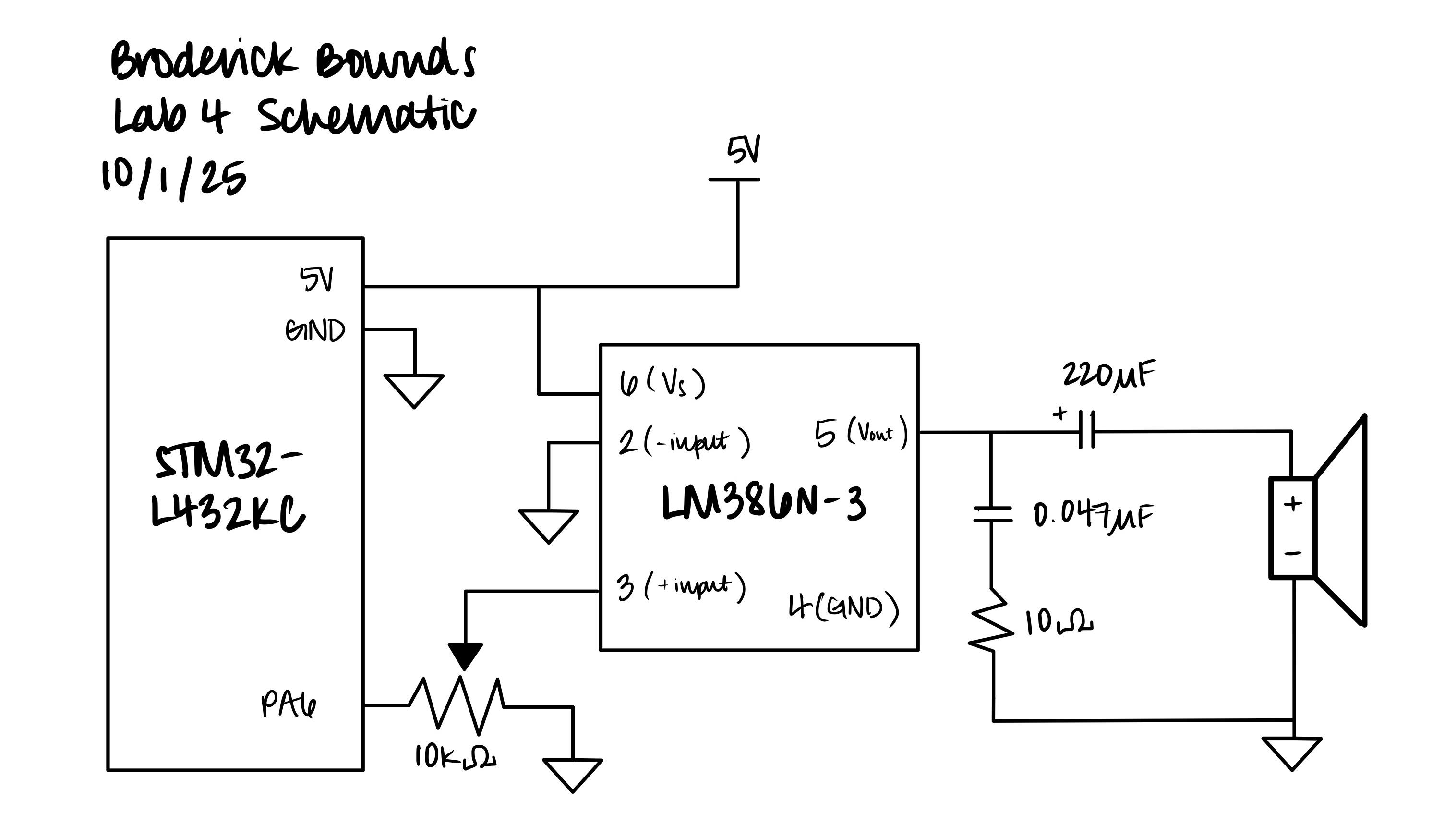
Figure 1: Schematic of the physical circuit layout of the STM32L432 Board and the LM386N audio amplifier.
Calculations and Results
To verify the performance of our design, we calculated the ranges of frequencies and durations supported by our timer configuration. With a system clock of 80 MHz and using a prescalar of 79, \[ PSC = 79 \quad \Rightarrow \quad f_{\text{tick}} = \frac{80{,}000{,}000}{79+1} = 1{,}000{,}000 \, \text{Hz} \] the timer increments every $1 , s$.
Minimum Frequency
The maximum auto-reload value on a 16-bit timer is \(ARR_{\max} = 2^{16} - 1 = 65{,}535\) which corresponds to a minimum frequency of \[ f_{\min} = \frac{f_{\text{tick}}}{ARR_{\max} + 1} = \frac{1{,}000{,}000\ \text{Hz}}{65{,}536} \approx 15.26 \, \text{Hz}. \] Thus, our design can reliably produce pitches as low as ~15 Hz.
Maximum Frequency
The smallest valid ARR value is 1, which gives: \[ f_{\max} = \frac{f_{\text{tick}}}{ARR_{\min} + 1} = \frac{1{,}000{,}000}{2} = 500{,}000 \, \text{Hz} = 500\ \text{kHz}. \]
Therefore, the minimum and maximum frequencies that be played are 15 Hz and 500 kHz. This is far above the audio range, so any audible note (20 Hz – 20 kHz) should be fully captured.
Minimum Duration
The timer’s resolution is one tick: \[ARR_{\min} = {f_{\text{tick}} \times t_{\min} } = 0 \quad \Rightarrow \quad t_{\min} = 0\text{ms}. \] This means we can produce rests or note durations as short as one microsecond, though in practice this is limited by the speed of audible perception.
Maximum Duration
For long delays (rests or note holds), we use TIM15 with the same tick frequency. The maximum delay is when \(ARR_{max} = 65535\) : \[t_{\max} = (ARR_{\max} + 1) \times f_{\text{tick}} = 65536 \times 1\ \text{MHz} \approx 0.0655\ \mu\text{s} = 65.5 \, \text{ms}. \]
If longer note durations are required, we can extend them by looping multiple timer intervals.
Oscilliscope Traces of Frequencies
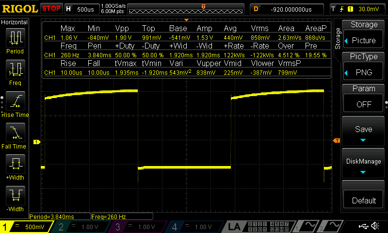
Figure 2: Oscilloscope capture of a note coded at 262 Hz, measured at 260 Hz. The small difference (≈ 0.76% error) is well within the ±1% accuracy requirement.
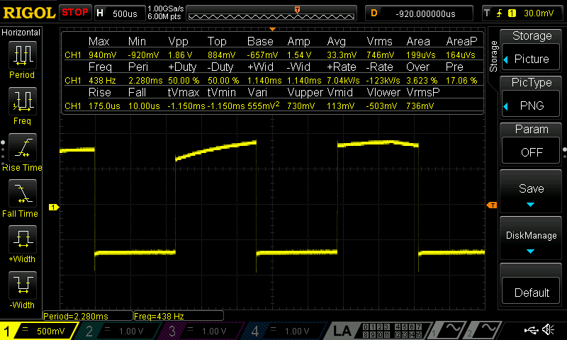
Figure 3: Oscilloscope capture of a note coded at 440 Hz, measured at 438 Hz. The frequency deviation (≈ 0.45% error) also satisfies the requirement of less than 1% error.
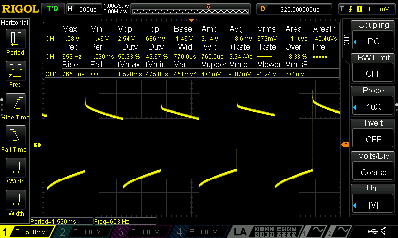
Figure 4: Oscilloscope capture of a note coded at 659 Hz, measured at 653 Hz. The difference (≈ 0.91% error) remains within the ±1% specification.
Verifying of Pitch Accuracy
To calculate and validate pitch accuracy across our range (220 – 1000 Hz) we can first evaulate our ARR value with the desired frequency and then move backwards and plug in a rounded down value of ARR due to the hardware imperfections: \[ARR = \frac{f_{\text{tick}}}{f_{out}} - 1 \]
So therefore, starting with the lower end of the frequency range at 220 Hz, \[ ARR = \frac{1\ \text{MHz}}{220\ \text{Hz}} - 1 =4544.\overline{45} \]
Now we can utilize this ARR value and say due to imperfections in hardware and/or software we can round down our ARR value to the nearest integer and then plug it in and see what our actual frequency is, \[ {f_\text{des}} = \frac{f_\text{tick}}{ARR + 1} = \frac{1 \text{MHz}}{4545} = 220.022\ \text{Hz} \]
Now utilize both the expected and desired frequencies to calculate the percent error, \[ \frac{220.022\ \text{Hz} - 220\ \text{Hz}}{220\ \text{Hz}} = 0.0001 = 0.01\% \]
Now we can calculate with our higher end frequency of 1000 Hz using the same method: \[ ARR = \frac{1\ \text{MHz}}{1000\ \text{Hz}} - 1 = 999 \]
Becuase our ARR value is an integer value, theoretically there should be no percent error due based on previous remarks of rounding down decimal values. So our percent error would be zero \[ {f_\text{des}} = {f_\text{exp}}\quad \Rightarrow \quad = 0\% \]
With these calculations, I demonstrated the timer supports all required note frequencies and durations. The pitch accuracy is at least within \(1\%\) across the target range. Rests (when frequency = 0) are correctly implemented by disabling the channel output.
Conclusion
This lab demonstrated how to use the STM32L432KC microcontroller to generate music through timers, PWM, and GPIO. The design successfully played Für Elise at the correct tempo and pitch accuracy, with proper rests. For extension, the design also played the Star Wars theme, and a potentiometer was added for volume control. Frequency accuracy were in range of 1%. I spent approximately 17 hours completing this lab, including datasheet reading, code debugging, and oscilloscope testing.
AI Prototype Summary
When I used ChatGPT to help me code for the STM32L432, I found the output surprisingly effective. The explanations were written in a way that pulled together both the math (timer frequency formulas) and the hardware setup steps (registers, GPIO alternate functions). In some cases, this was faster and clearer than digging through the reference manual on my own, since the manual is dense and not always organized around the specific use case I had in mind. For instance, the LLM explained the relation between PSC, ARR, and the timer input clock in one concise formula, something I would have had to piece together across multiple sections of the manual. This is once I uploaded the manual as reference.
For timers, it provided a full recipe with both math and register workflow. So I’d rate it more useful as a teacher than as a pure document search engine.